Quick Start Guide
Packing List
Please check the delivered equipment against the list below. If anything is missing, contact the shipper immediately.
| No. | Equipment / Accessory | Qty | Description |
|---|---|---|---|
| 1 | Conference Host (MCU) | 1 unit | System core: mixing, microphone management, network forwarding |
| 2 | Wireless Microphone | 4 pcs | Delegate microphones; one can be configured as chairman microphone |
| 3 | Wireless AP | 1 unit | 5GHz WiFi access point for wireless microphone connection |
| 4 | POE Switch | 1 unit | Powers the AP and connects to the host |
| 5 | Network Cable | 3 pcs | AP-to-switch, switch-to-host, management PC |
| 6 | Audio Cable | 1 pc | Connects host AUDIO OUT to sound reinforcement equipment |
| 7 | Host Power Cord | 1 pc | 220V power input |
| 8 | AP Power Adapter (if switch does not support POE) | 1 pc | Backup power supply |
If your order includes wired microphones, cameras, or central control devices, please check them together and refer to the User Manual for connection instructions.
Equipment Overview
- Conference Host: The core controller of the system. The front panel includes the power button, STATUS indicator, UNIT wired channel indicators, etc.
- Wireless Microphone: Used by participants to speak. After power-on, it automatically searches for the AP and registers to the host.
- Wireless AP: Provides a 5GHz WiFi network for microphones to access the system.
- POE Switch: Powers the AP and transmits data via network cable.
- Sound Reinforcement Equipment: Power amplifier, speakers, etc., receiving audio output from the host.
System Connection
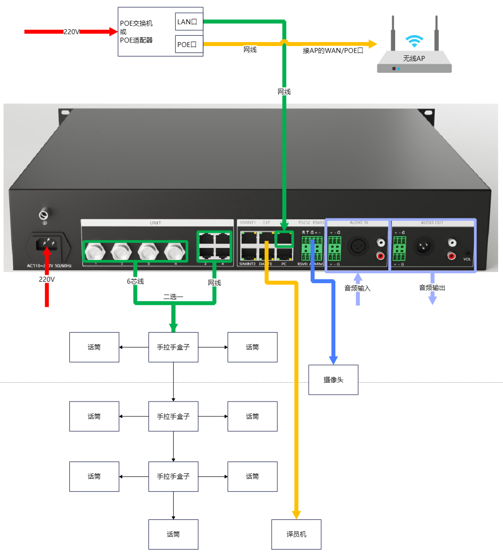
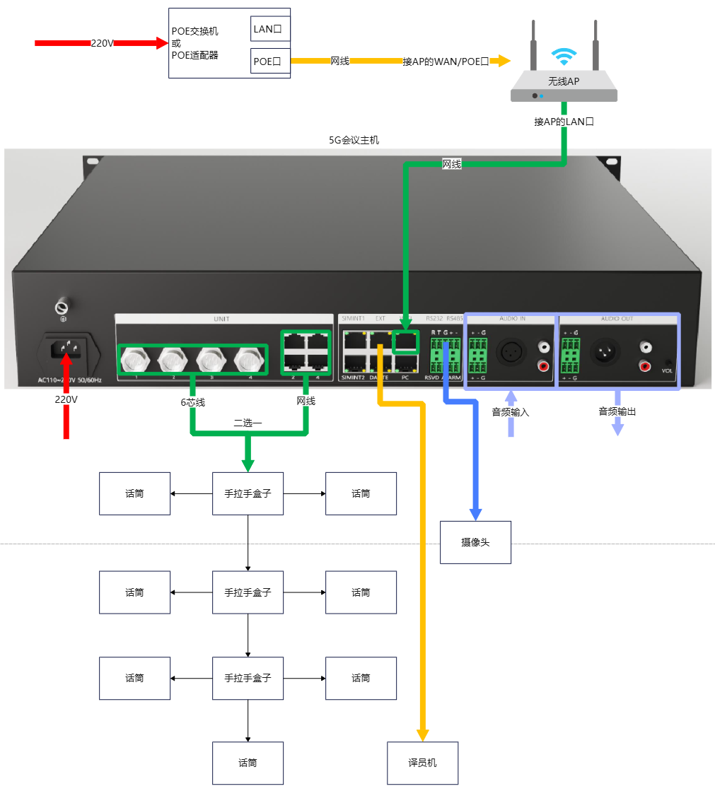
Connect the system according to the following steps: Install AP, microphones, and main unit in place Connect AP to POE switch (or POE power supply) via network cable Connect POE switch to main unit's WIFI port via network cable Connect wired microphones to main unit's UNIT1-4 aviation connectors or RJ45 network ports via dedicated cables (optional step) Connect main unit to sound reinforcement equipment via audio cables Connect main unit to cameras or central control via RS232 or RS485 serial cables Deploy console and conference management platform to a Windows computer (optional operation) Connect power cord to main unit power interface
- System installation and use environment should maintain cleanliness and appropriate temperature/humidity, with good ventilation and no blocked ventilation holes - All power switches, plugs, sockets, and power cords of system equipment must ensure electrical safety - Connect peripheral devices first, then power on the system. - If problems occur, please refer to the "FAQ" chapter; if unresolved, contact manufacturer service personnel.
Recommended Connection Order
Step 1: Place the AP, host, and sound reinforcement equipment
Step 2: Connect all network cables (do not power on yet)
Step 3: Connect the audio cable
Step 4: Finally, power on the equipment
System Registration
This system uses a registration code mechanism for license management. Scenario descriptions are as follows: New devices have a default 3-month trial period after flashing, calculated from the flashing date After expiration, can decide whether to allow customer to continue trial and for how long After customer confirms purchase, or when permanent use authorization is deemed appropriate, generate permanent registration code For 2 and 3 above, use https://zc.randvision.cn to register Registration code input methods: Method 1: - Click main unit display → "Settings" → "Registration Code", provide machine code, microphone quantity, and trial duration to manufacturer personnel. After response, click input box and enter registration code Method 2 (Recommended): - Connect computer, mobile phone, or tablet to AP or main unit EXT/LAN port (i.e., on same network as main unit), open browser, log in to main unit web interface http://192.168.10.111, click "Settings" → "Registration Code" input box on webpage, paste and click "OK" to quickly input registration code
After registration code is entered, main unit will automatically restart
Wired Channel Selection (Optional Step)
Click main unit display → "Settings" → "Wired Microphone Channel", click to select whether each channel uses GX16 aviation connector or RJ45 network port
⚠️ DANGER: Do not connect ordinary network devices to main unit's UNIT RJ45 network ports, as this may cause equipment damage.
Power-On and Self-Check
Power-On Sequence
- Turn on the POE switch first and wait for the AP to start up (about 1~2 minutes);
- Turn on the host power. The front panel POWER light should stay on;
- Wait for the STATUS light to flash at 1-second intervals, indicating normal operation;
- Turn on the wireless microphones. The microphone indicator lights will turn on first and then go off after connecting to WiFi.
Indicator Light Meanings
| Indicator | Status | Meaning |
|---|---|---|
| Host POWER | Steady on | Power normal |
| Host STATUS | 1-second flash | Normal operation |
| Host STATUS | Off or fast flash | Abnormal; check network cable or contact after-sales |
| Microphone indicator | On then off after startup | Connected to WiFi and host |
| Microphone indicator | Continuous flashing | Not connected to network or host |
| Microphone speaking light | Steady red | Currently speaking |
Confirm Host Is Online
On the management computer, open a browser and visit:
http://192.168.10.111
If the host Web management page appears, the network connection is normal.
If it cannot be opened, confirm that the computer and host are on the same network segment, or try connecting the computer directly to the host EXT/LAN port.
Simple Loopback Test
After connecting cables according to System Connection chapter, power on AP, microphones, and main unit in sequence Local audio loopback: Connect audio source to main unit's AUDIO IN interface, and test if AUDIO OUT has sound output Microphone network loopback: Confirm microphone is connected to network and main unit, then click microphone's "Speaking" button for sound test
- When microphone powers on, it will light up the microphone boom indicator and speaking indicator until WIFI connection is established, then they turn off - When main unit powers on, it will wait for valid network cable insertion in WIFI network port before normal operation; thereafter, front panel STATUS indicator will flash at 1-second intervals
Setting Microphone Roles
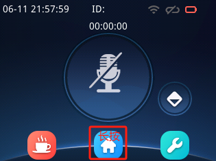
For microphones without display, hold speaking button while powering on to change role (cycles through "Delegate → Chairman → Delegate → …") For microphones with display, after entering microphone display home page, long press "HOME" button for 5 seconds or more to change role
When chairman microphone powers on, all indicators will flash rapidly 3 times to indicate chairman status.
Conference Modes
Free: Delegate and chairman microphones are only limited by maximum number of speakers FIFO (First In First Out): The last speaking microphone will replace the earliest speaking microphone; delegate microphones cannot replace chairman microphones Restricted: Delegate and chairman microphones are only limited by maximum number of speakers Request: Chairman speaking is unrestricted. When delegate microphone clicks to speak, it first sends request to all online chairmen. If any chairman approves, delegate microphone enters speaking state; if any chairman rejects or all chairmen ignore, delegate microphone returns to standby state
Currently, request mode only allows one delegate microphone to initiate request at a time; other delegate microphones will be forcibly canceled when initiating request
AI Voice Control: Any microphone opens microphone when picking up human voice
ID Assignment
Click main unit display → "Settings" → "Assign ID", click to input starting number, click "Start" Click edit button on each microphone display in sequence to complete ID assignment for that microphone After completion, click "Stop" on main unit display
- If microphone IDs are duplicated after power on, first turn off all microphones, then re-assign ID to the microphone with conflict prompt - If the main unit and conference room are not in the same room, access the main unit web backend over the network and initiate the ID assignment operation
Setting Microphone IP
If microphone display prompts IP Conflict or all indicators flash rapidly after microphone powers on, this indicates IP conflict with another microphone. No action is needed; the microphone will automatically restart and update its own IP
This method is only applicable to wired microphones
Speaking/Exit Speaking
When network is connected and main unit is connected in microphone display, click microphone icon on home page to speak/exit speaking
If microphone has touch switch or light-touch button, it can also be used for speaking/exit speaking
Chairman Priority
When microphone role is chairman, priority function can be used. Specific operation methods are as follows: For microphones without display, long press speaking button for 3 seconds to trigger priority function For microphones with display, long press speaking button for 3 seconds, or click priority icon on display to trigger priority function
Setting System Time
When console connects to main unit, main unit synchronizes time with console's computer or tablet Time can be set manually via main unit display → "System Settings" → "Time Settings" Time can be set automatically via main unit web backend → "Main Unit Settings" → "Time Sync"
Only need to set main unit time; microphones will automatically synchronize time when connecting to main unit
Multi-language Settings
Set via main unit web backend → "Advanced Settings" → "Language Settings"
After setting, the main unit and all online microphones will be configured and will restart
Quick FAQ
Q1: Host STATUS light does not flash
- Check whether the network cable to the host WIFI port is securely connected;
- Confirm that the AP and switch have started normally;
- Try restarting the host.
Q2: Microphone cannot connect to WiFi
- Confirm the AP is powered on and the WiFi name is correct;
- Check whether the distance between the microphone and AP is too far;
- Confirm the microphone system version matches the host (check OID/MID before factory reset).
Q3: No sound output when speaking
- Check whether the rear panel volume knob of the host is turned on;
- Confirm the audio cable is correctly connected from host AUDIO OUT to sound reinforcement equipment;
- Check whether the system is in trial period or registered.
Q4: Multiple microphones have ID conflicts after power-on
- Turn off all microphones and power them on one by one;
- Or use the host display "ID Assignment" function to reassign IDs.
Further Support
If you still cannot resolve the issue after following this document, please contact the manufacturer after-sales service or refer to the "System Maintenance" chapter in the User Manual.
It is recommended that technical personnel walk through this document completely before the first demo to ensure all equipment is in normal condition.