Advanced Settings
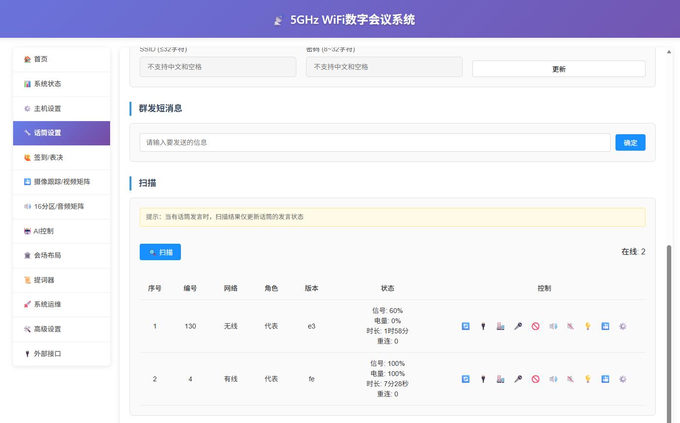
Microphone Management
- Connect the computer to the wireless AP (for account/password, refer to the relevant section), and ensure the computer is on the same IP subnet as the main unit;
- Open the main unit web backend → "Microphone Settings" → "Scan", wait 3 seconds to scan and operate the microphones;
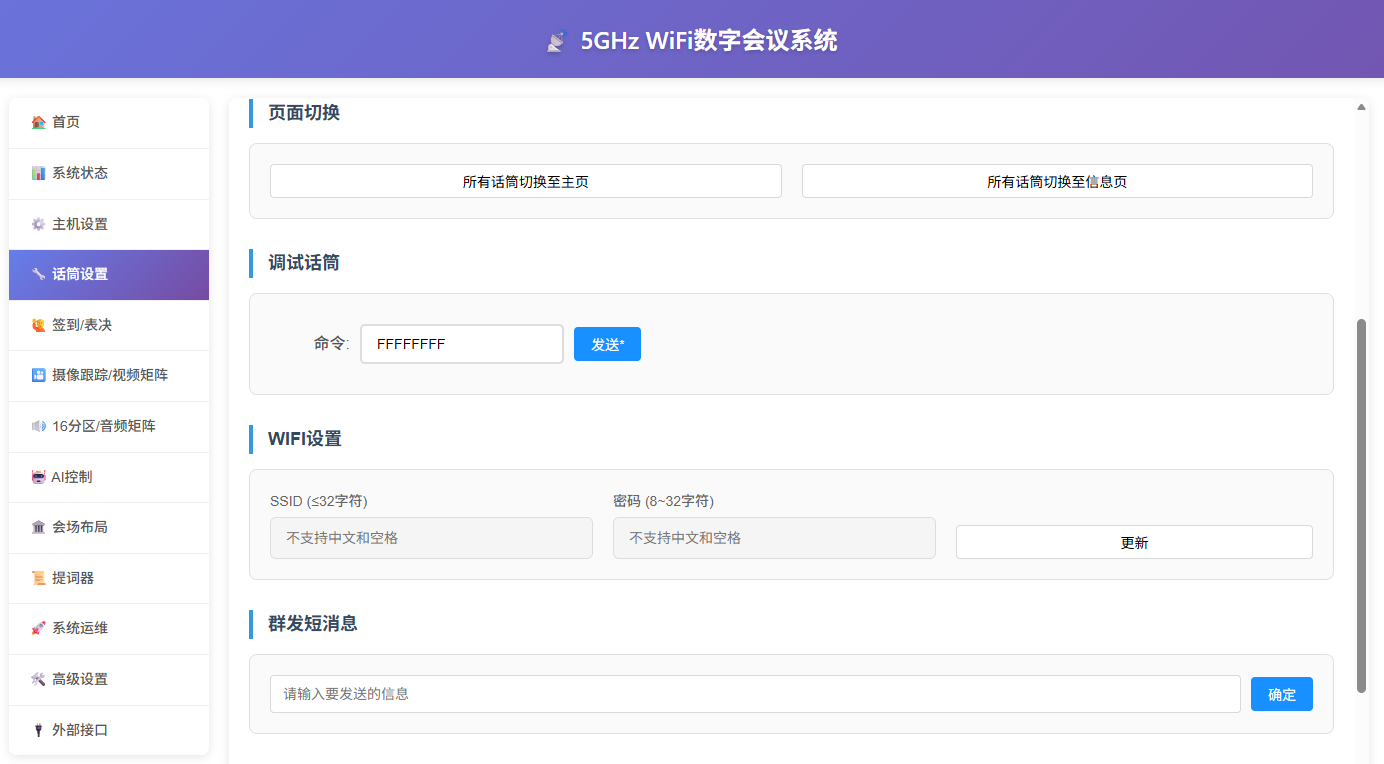
Changing WiFi Name and Password
- Turn on all microphones whose WiFi name needs to be changed;
- Open the main unit web backend → "Microphone Settings" → "WiFi Settings";
Scenario 1: Only one AP on site, set the AP to a new SSID and password
- Enter the new SSID and password in the page above, click "Update". After the microphones update, they will automatically reconnect to the new SSID;
- Enter the AP backend and set it to the new SSID and password;
- Set the new AP's SSID and password, and restart it;
- Confirm the AP is working normally, restart the microphones, and they will connect to the new SSID;
Scenario 2: Two APs on site, remove the old AP and replace it with a new one
- Enter the new AP backend and set it to the new SSID and password;
- Wait until the new AP signal is stable (the computer or mobile phone can scan it);
- Enter the new SSID and password in the page above, click "Update". After the microphones update, they will automatically attempt to reconnect to the new AP;
- Turn off the old AP power;
Scenario 3: Multiple APs on site, set different SSIDs to distinguish them
- First turn off the other APs, leaving only one AP on;
- Fully execute all operations of Scenario 1 in sequence;
- Then repeat all operations of Scenario 3 for the remaining APs;
- If after confirming the new AP signal is stable (the computer or mobile phone can scan it), the microphone still has not connected to the new AP, reset it and continue connecting;
- To restore the factory SSID and password, please refer to the "Factory Reset" chapter;
Multi-AP Extension
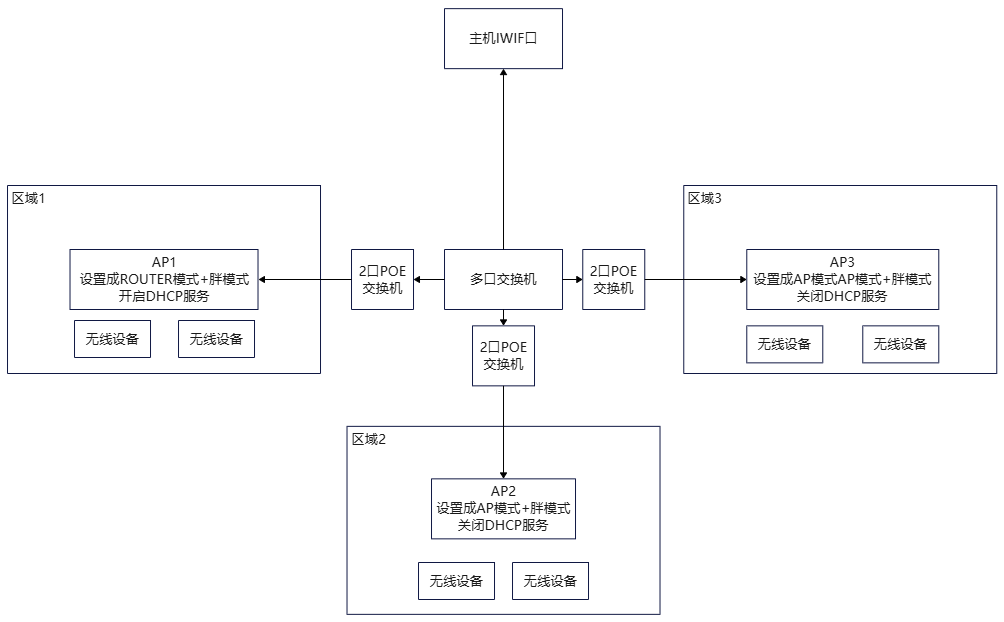
When the conference room area is too large, or when wanting to connect microphones from multiple conference rooms to the same main unit, the multi-AP extension function can be used to expand the access range of the 5G WiFi AP. The network topology is shown below (taking the latter as an example):
In this network topology, no other routers should be connected to the switch;
The specific operation process is as follows:
- Turn off AP2, AP3…APn, turn on AP1, and directly import the factory configuration;
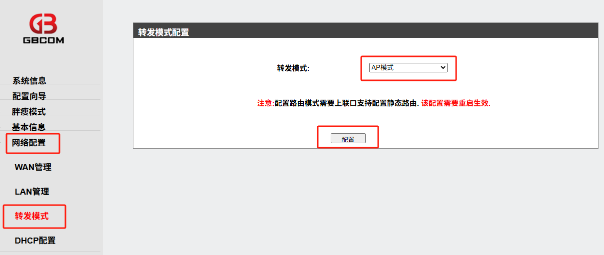
- Turn off AP1, turn on AP2, first import the factory configuration, then log in again, and then change the AP to "AP Mode" as shown below, and confirm;
- Similarly, set AP3…APn;
Hiding the WiFi Network
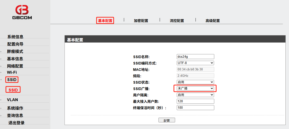
For confidentiality requirements, the WiFi name can be hidden. The specific operation methods are shown below:
- Hide 2.4G WiFi
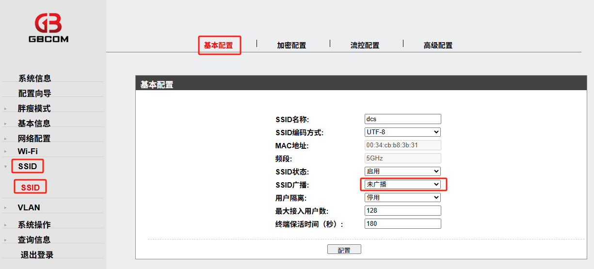
- Hide 5G WiFi
Camera Tracking (Main Unit)
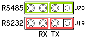
- Set the jumper caps on the main board to select the control protocol for the camera;
Select RS485: short the green part and disconnect the red part;
Select RS232: short the red part and disconnect the green part;
- Connect the main unit's RS232 interface to the camera (or connect RS485 to multiple cameras, ensuring + to + and - to -, and do not reverse the polarity);
- Connect the computer to the same network as the main unit;
- Open the main unit web backend → "Camera Tracking / Video Matrix", as shown below;
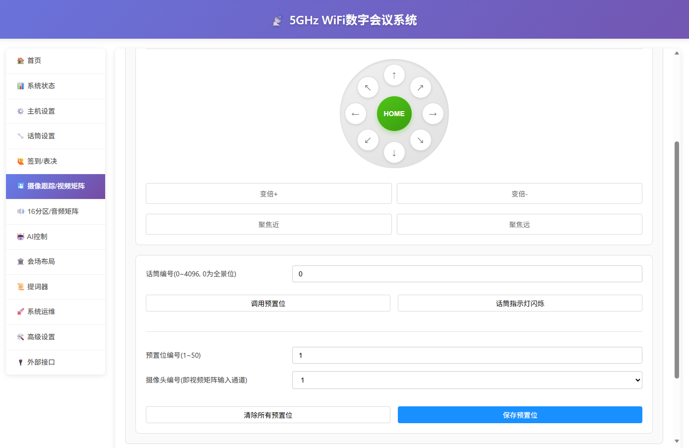
- Set "Camera Number (must match the camera-side number)", "Baud Rate", and "Camera Protocol", then click the PTZ move buttons on the right to first confirm whether the camera can move normally;
Scenario 1: Setting a new preset position
- Set "Microphone Number", "Camera Number", and "Preset Number", move the camera to the predetermined position, and click "Save Preset";
If the preset number is saved repeatedly, the latest preset position shall prevail;
Scenario 2: Adjusting a previously set preset position
- Enter the "Microphone Number" to be adjusted, click "Call Preset", and the corresponding microphone indicator lights up. If a preset was previously set, the camera will move to the predetermined position at this time. You can move it to the specified position again, then click "Save Preset". The corresponding microphone indicator turns off, and this operation will overwrite the previous record;
- "Turn On/Off Microphone Indicator" is only used to assist in indicating the microphone position and has no other purpose;
- After camera tracking is set, re-assigning IDs does not require re-setting camera tracking;
- To re-set all preset positions, click "Clear All Presets";
- When used with the built-in 4x4 matrix, the camera numbers must be 1, 2, 3, 4, corresponding to HDMI1 IN, HDMI2 IN, HDMI3 IN, and HDMI4 IN connected to the matrix input;
Camera Tracking (Central Control)
- If the site is additionally equipped with central control equipment and camera linkage needs to be controlled through the central control equipment, the main unit and the central control can be networked as follows:
- Connect the main unit and the central control to the same network;
- Set the central control IP to 192.168.10.222, port 20000, protocol UDP;
- When a microphone speaks, the main unit will send a UDP message via the network to 192.168.10.222:20000. The message content is the ID number of the microphone with its microphone open;

Attendance Check-in
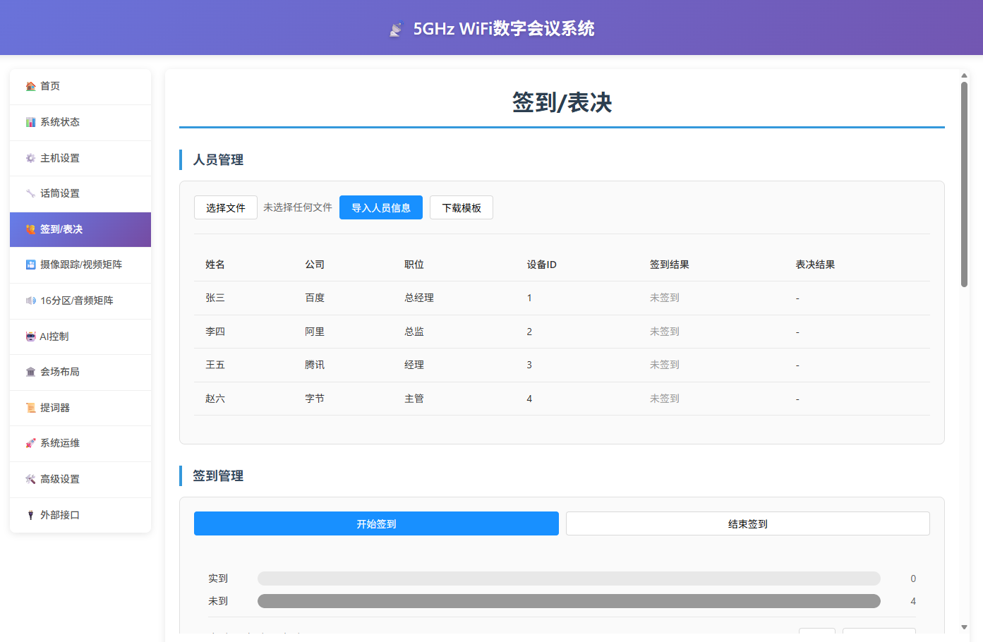
- Access the main unit web backend;
- Manage participants;
- Download the template → Edit the participant name, company, position, and corresponding microphone ID → Import personnel information;
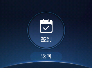
- Initiate check-in;
- Click "Initiate Check-in". The microphone display will show the check-in page. After the user clicks check-in, it returns to the home page indicating successful check-in;
Voting / Ballot / Rating
- Access the main unit web backend;
- Add a custom vote;
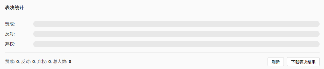
- Add a vote/ballot as shown below. A maximum of 6 options is allowed, and each option may contain up to 4 Chinese characters or 8 English characters;
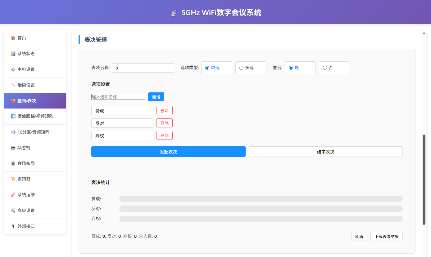
- Initiate voting;
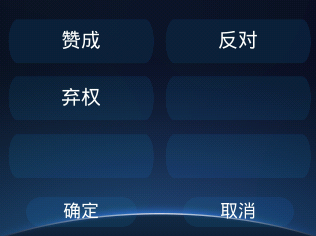
- Click "Initiate Voting". The microphone display will show the voting page. After the user clicks an option and confirms, it returns to the home page shortly (you can re-select and confirm, and the final selection shall prevail);
- End voting;
- After the microphones vote one by one, click "Refresh" to display the voting results, as shown below:
WiFi Selection
- Enter the microphone display "Settings Page" → "Brightness", and long press the "Settings" button for more than 5 seconds. The microphone will switch to the WiFi selection page;
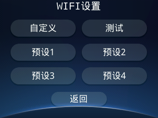
The buttons are defined as follows:
- Custom: saved here when a custom SSID and password are set via the web page / console;
- Test: the default dcs WIFI;
- Presets 1~4: factory-preset WiFi, corresponding to the format xxx, xxx_2, xxx_3, xxx_4;
Voice Transcription (Optional)
- Enter the microphone display "Settings Page" → "Microphone Settings", and long press the "Settings" button for 5 seconds or more. The microphone can switch to the voice transcription text display page;
SDK Integration
- The main unit can provide a UDP/HTTP protocol SDK for third-party device calls. Available calls include: querying main unit status, getting the microphone list, check-in, voting, voting linkage, etc. For details, please consult the pre-sales technical engineer;
System Information Page
Microphones with a display and the main unit use the information page to display system status and operation information. The meaning of each field is explained as follows:
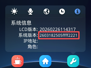
- LCD Version: Current display version;
- System Version: Current system version. After OTA upgrade, you can verify it here;
- IP Address: Microphone IP address + first character of the AP signal name;
- Role: Chairman / Delegate / Interpreter;
The system version format is defined as follows:
- 260318: Software version timestamp;
- 25: Software version unique number;
- 05: Hardware version number;
- ff: Reserved;
- ff: Reserved;
- 22: Microphone LCD type;
- 2: Button type;
- 1: Battery quantity;
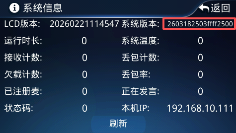
For the main unit:
- LCD Version: Current display version;
- System Version: Current system version. After OTA upgrade, you can verify it here;
- Runtime: Cumulative time since system power-on, unit is seconds;
- System Temperature: Temperature of the system core components. It is recommended not to exceed 60 °C;
- Receive Count: Total number of audio data packets received cumulatively by the main unit;
- Packet Loss Count: Total cumulative packet loss when the main unit receives audio;
- Underrun Count: Total cumulative count when audio data packets are not delivered in time when needed by the main unit;
- Packet Loss Rate: Cumulative packet loss count / cumulative total received audio count, unit is 1/10000;
- Registered Mics: Number of microphones connected to the main unit;
- Currently Speaking: Number of microphones currently speaking;
- Status Code: Indicates system status. Please refer to the Status Code Description chapter;
- Local IP: Main unit IP address;
The system version format is defined as follows:
- 260318: Software version timestamp;
- 25: Software version unique number;
- 03: Hardware version number;
- ff: Reserved;
- ff: Reserved;
- 25: Main unit LCD type;
- 0: Reserved;
- 0: Reserved;