System Maintenance
Factory Reset
Microphone Factory Reset
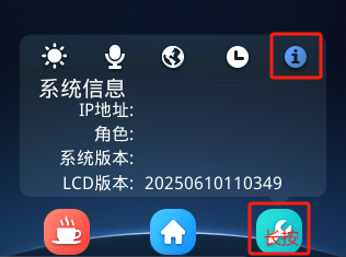
On the microphone display, tap "Settings" → "System Information", then press and hold the "Settings" button for 5 seconds or more (see the figure below). The microphone will restore factory settings and restart automatically. The following items will be restored:
- ID number;
- Role;
- Microphone gain;
- Display brightness;
- Standby wait time;
- WiFi name and password changed after delivery;
- Microphone IP changed after delivery (wired microphones only)
Before a factory reset, be sure to confirm that the OID and MID in "Settings" → "System Information" → "System Version" meet the requirements (refer to Question 1 in the FAQ); otherwise, the microphone may fail to connect to WiFi;
Main Unit Factory Reset
On the main unit display, tap "System Settings" → "Main Unit Settings Information", then press and hold the "Factory Reset (3S)" button for 3 seconds or more. The main unit will restore factory settings and restart automatically. The following items will be restored:
- Conference mode;
- Maximum number of speakers;
- Speaking countdown mode and time;
- Camera tracking settings;
Microphone Firmware Upgrade (OTA Method)
Preparation
- Several microphones to be upgraded (with power supplies);
- One wireless AP (for upgrading wireless microphones), or one network cable;
- One Windows 10/11 computer;
- One web plugin (
File Server\common\webPackage\DCSResourceServer_Setup_xxx.exe); - One microphone firmware file xxx.bin (
File Server\massProduction\Microphone\Wireless (or Wired) Main Board\OTA Upgrade Firmware\);
Operation Steps
- Install the web plugin;
- Connect the computer to the wireless AP (for the account and password, refer to the relevant section), or connect it to the EXT/LAN port of the main unit via a network cable — in short, make sure the computer and the devices to be upgraded are on the same network;
- Access the main unit web backend at http://192.168.10.111;
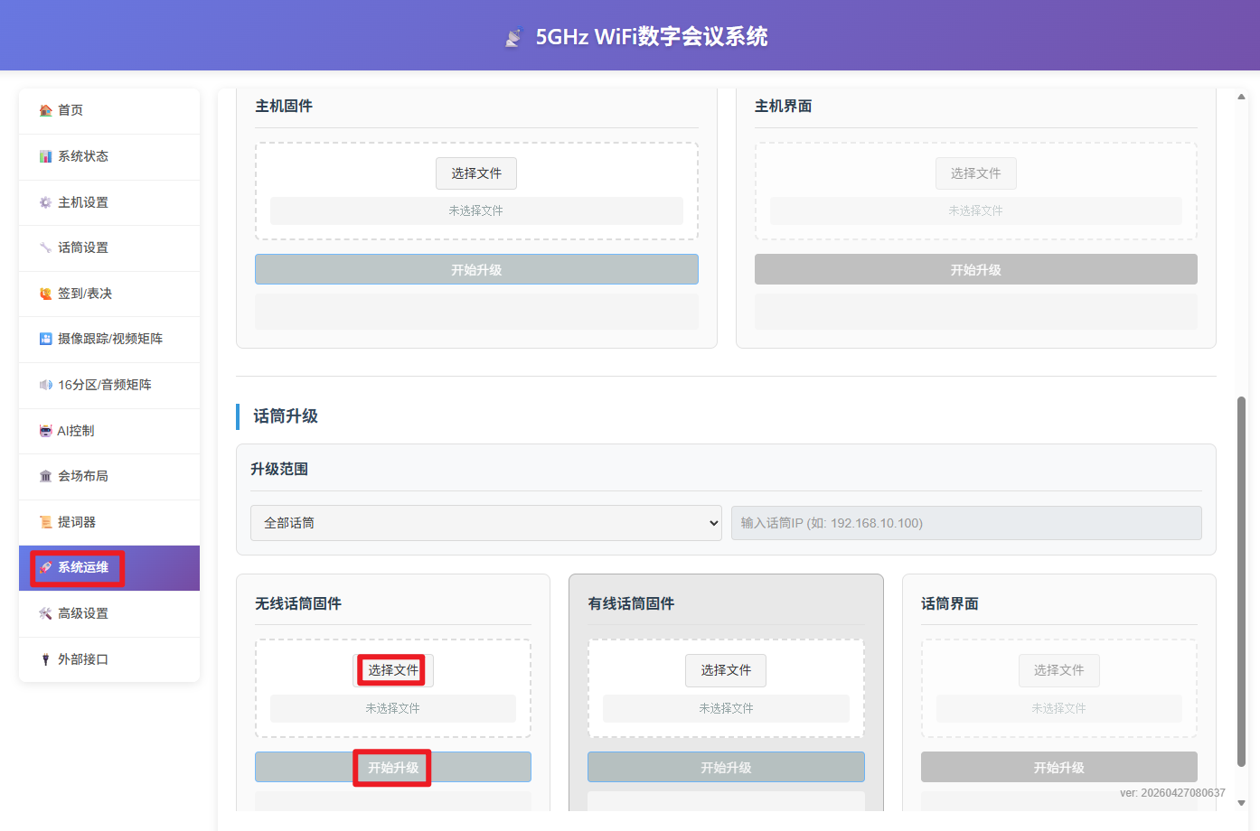
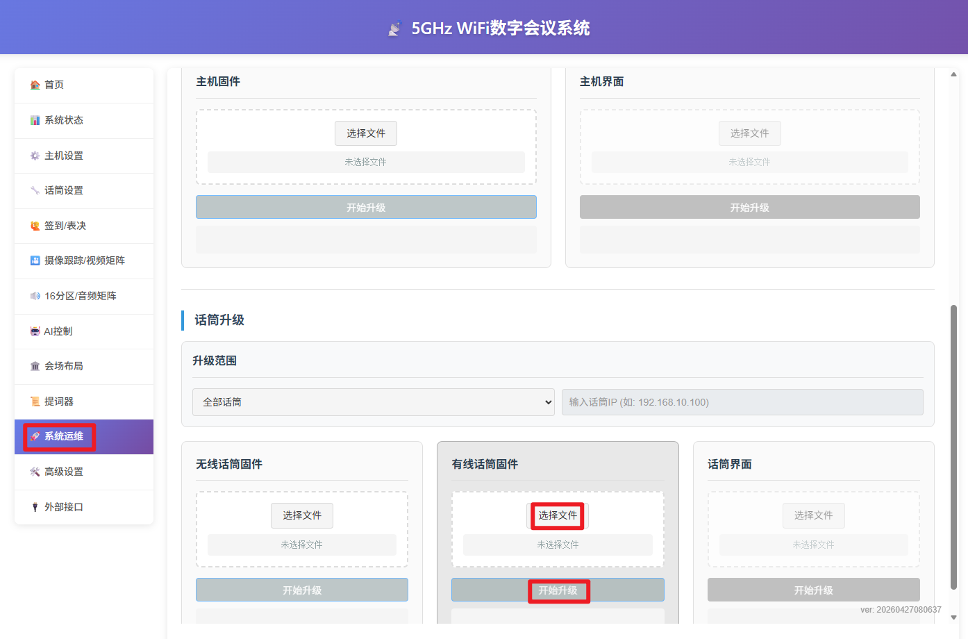
Note 1: If you connect to the wireless AP, it is recommended to first disable the computer's firewall and forget any previous WiFi networks; otherwise, after the computer has been connected to the AP for a while, the loss of internet access may cause the system to automatically switch the network back to the original WiFi, which in turn causes the upgrade to fail; Note 2: When the computer has multiple network adapters, it is recommended to disable the other adapters and keep only one before connecting to the AP; Note 3: If the microphone's "System Version" is earlier than 260501, you must use a console version earlier than "Console_20260501" to upgrade the microphone firmware;
-
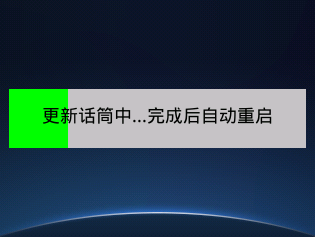
Select the microphone firmware and click Upgrade. The microphone upgrade completes in about 10 seconds, after which the microphone restarts automatically;
-
If the network is interrupted or an exception occurs during a wireless microphone upgrade, the error prompt shown below appears and the mic stem indicator changes color. In this case, simply make sure the network is normal and start the upgrade again:
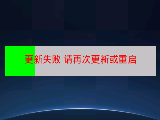
-
If the network is interrupted or an exception occurs during a wired microphone upgrade, or the upgrade has still not succeeded after more than 5 minutes, follow these steps:
-
Set the computer's IP to 192.168.10.110, then go to the main unit web backend → "System O&M" → "Wired Microphone Firmware Upgrade", select the firmware, and start the upgrade service again;
-
Power off the wired microphone, press and hold the button on the side of the microphone, and then power it on again. The microphone now enters OTA mode, and all indicators keep flashing rapidly;
-
Once the microphone enters the upgrading state, the indicators stop flashing rapidly; simply wait for the upgrade to complete;
-
If the upgrade succeeds, the microphone restarts automatically. On the microphone display, tap "Settings" → "System Information" and check whether the "System Version" on the system information page has been updated to the latest:
If there are many microphones, the following batch checking methods are recommended:
- Main unit web backend → "Microphone Settings" → "Switch to Information Page" (recommended; suitable when the number of microphones is moderate and they can be checked one by one);
- Main unit web backend → "Microphone Settings" → "Scan", and observe the microphone versions in the scan results (requires the main unit to be online; suitable when there are too many microphones to check one by one);
Display Firmware Upgrade (OTA Method)
Preparation
- The previous version of the display firmware (assumed to be private_pre)
- The latest version of the display firmware (assumed to be private_now)
- Other requirements are the same as in the "Microphone Firmware Upgrade" section;
Operation Steps (Recommended to Be Performed by the Manufacturer's After-Sales Personnel)
- Turn on the display of the microphone or main unit, take a photo of the "Settings" → "System Information" page, and send it to the manufacturer's after-sales personnel for confirmation;
Make sure the display specifications (brand, model, size, etc.) of all devices to be upgraded are identical;
- Open the main unit web backend → "System Maintenance" → "Main Unit or Microphone Display";
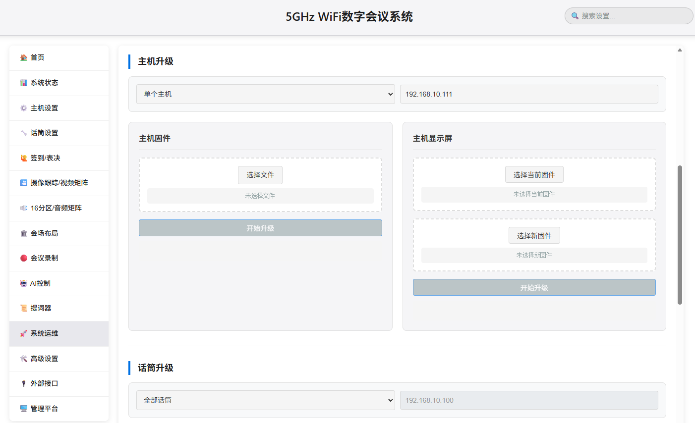
- Select the previous-version display firmware (if not selected, all files are upgraded by default) and the latest-version display firmware, then click Upgrade. All microphones will enter the upgrade page and the mic stem indicators will light up, as shown below:
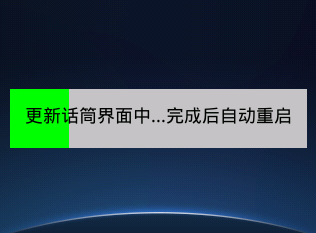
- If the upgrade succeeds, the microphone restarts automatically. On the microphone display, tap "Settings" → "System Information" and check whether the "LCD Version" has been updated to the latest, as shown below:
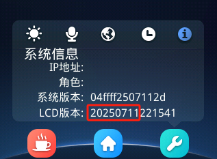
- The LCD version format is defined as follows:
- 20250711: year, month, day;
- 221541: hour, minute, second;
- During a batch display firmware upgrade, if individual microphones fail to upgrade, simply power off the microphones that have already been upgraded, restart the remaining microphones, and run the upgrade again;
Microphone Display Firmware Upgrade (TF Card Method)
Preparation
- Several microphones to be upgraded (with power supplies);
- One computer;
- One TF card, 8–128 GB, formatted as FAT32 or exFAT;
- One card reader;
- The latest version of the display firmware (
File Server\xxx Dedicated Directory\Production Materials\Customization\Display Firmware\Microphone_xxx\private);
Operation Steps
- On the computer, extract the display firmware into a folder named private (the name must be exactly the same) and copy it to the root directory of the TF card;
- Insert the TF card into the TF card slot of the microphone;
- Power on the microphone to start upgrading the display firmware;
- When the display indicates completion, power off the microphone, remove the TF card, and power the microphone on again;
- If the upgrade succeeds, on the microphone display tap "Settings" → "System Information" and check whether the "LCD Version" has been updated to the latest.
Main Unit Firmware Upgrade (USB Cable Method)
Preparation
- One main unit to be upgraded (with power supply);
- One Windows 7/10/11 computer;
- One USB cable;
- The MCUBootUtility.EXE software (
File Server\massProduction\Main Unit\mcu\OTA Upgrade Tool_mcuBootUtility\); - One main unit firmware file xxx.bin (
File Server\massProduction\Main Unit\mcu\Mass Production Flashing or OTA Upgrade Firmware\);
This upgrade method only supports main units with an OTA upgrade interface on the front panel;
Operation Steps
- Extract MCUBootUtility on the computer and open bin/MCUBootUtility.exe;
The directory where the software is stored must not contain Chinese characters; otherwise, flashing errors may occur;
- Plug one end of the upgrade cable into the computer and the other end into the OTA port on the front panel of the main unit, then power on the computer;
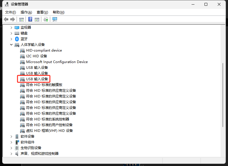
- Press and hold the START and STOP buttons on the front panel of the main unit at the same time, then turn on the main unit power. The computer will play a USB device insertion sound, and a "USB Input Device" will appear in Device Manager, as shown below:
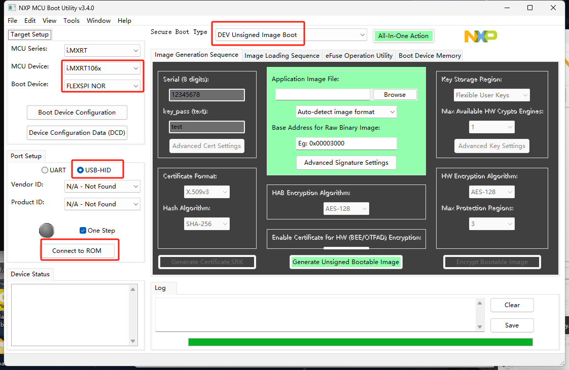
- Open the "MCUBootUtility.EXE" software, configure it as shown below, and click Connect to ROM;
- If everything is normal, it displays as shown below:
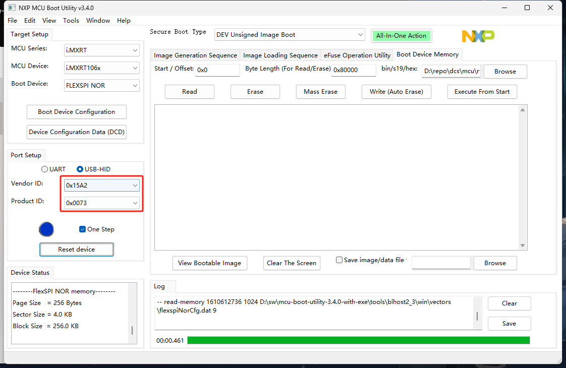
If an exception occurs, unplug and replug the USB cable, then try Connect to ROM again;
- Set the values as shown below (select the main unit firmware xxx.bin at bin/s19/hex), then click write (Auto erase) to start flashing. Flashing is complete when the green progress bar at the bottom finishes, as shown below:
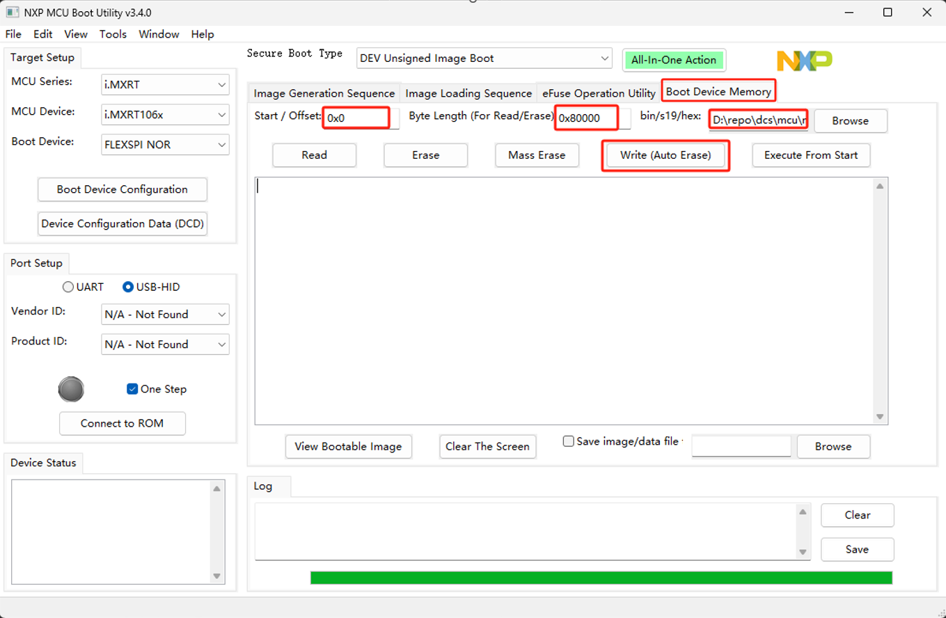
The directory where the firmware is stored must not contain Chinese characters; otherwise, flashing errors may occur;
- If the upgrade succeeds, on the main unit display tap "Settings" → "System Information" and check whether the "System Version" on the information page has been updated to the latest:
Main Unit Firmware Upgrade (OTA Method, Recommended)
Preparation
- The main unit to be upgraded (with power supply);
- One wireless AP (for upgrading wireless microphones), or one network cable;
- One Windows 10/11 computer;
- One web plugin (
File Server\common\webPackage\DCSResourceServer_Setup_xxx.exe) - One main unit firmware file xxx.bin (
File Server\massProduction\Main Unit\mcu\OTA Upgrade Firmware\);
Operation Steps
- Install the web plugin;
- Connect the computer to the wireless AP (for the account and password, refer to the relevant section), or connect it to the EXT/LAN port of the main unit via a network cable — in short, make sure the computer and the device to be upgraded are on the same network;
- Access the main unit web backend at http://192.168.10.111;
- Select the main unit firmware and click Upgrade. The main unit upgrade completes in about 10 seconds, after which the main unit restarts automatically, as shown below:
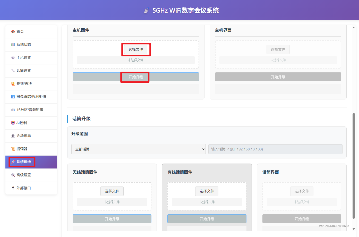
Only main units with versions later than 20260501 are supported; for earlier versions, please refer to the "Main Unit Firmware Upgrade (USB Cable Method)" section;
Main Unit Display Firmware Upgrade
Preparation
- One main unit to be upgraded (with power supply);
- One computer;
- One TF card, 8–128 GB, formatted as FAT32 or exFAT;
- One card reader;
- One display firmware package (
File Server\xxx Dedicated Directory\Production Materials\Customization\Display Firmware\MainUnit_xxx\private);
Operation Steps
- On the computer, extract the display firmware into a folder named private (the name must be exactly the same) and copy it to the root directory of the TF card;
- Insert the TF card into the TF card slot of the main unit's front panel display;
- Power on the main unit to start upgrading the display firmware;
- When the display indicates completion, power off the main unit, remove the TF card, and power the main unit on again;
- If the upgrade succeeds, on the main unit display tap "Settings" → "System Information" and check whether the "LCD Version" has been updated to the latest, as shown below:
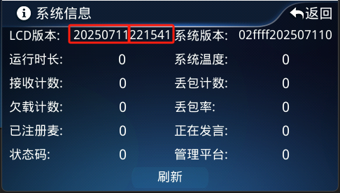
The LCD version format is as follows: 20250711: year, month, day; 221541: hour, minute, second;
Status Codes
Status Code Description for Microphones and the Main Unit
- This system uses status codes to indicate the current operating status of the system. The codes are listed in the table below:
| Code | Description | Solution |
|---|---|---|
| 0x1 | System not registered | |
| 0x2 | Microphone IP conflict | Wireless microphone: this issue generally does not occur; Wired microphone: the conflicting unit automatically updates its IP; if this does not work, set its IP individually |
| 0x4 | Microphone ID conflict | Set the ID of the conflicting microphone individually |
| 0x8 | Exceeds the maximum number of microphones the system can accommodate | Contact after-sales service personnel |
| 0x10 | Failed to read time | Is the MCU core board in debug state? Is the DSP core board inserted backwards? Is a DCS_SRV_MB_V305 or later main board paired with a front panel of a version lower than DCS_SRV_FP_V205? |
| 0x20 | Failed to read configuration | Same as 0x10 |
| 0x40 | For internal testing | |
| 0x80 | For internal testing | |
| 0x100 | Failed to parse the registration code | Is the registration code generator version correct? For versions before 20251114, use the v2 registration code generator For 20251114 (inclusive) and later, use the v3 or higher registration code generator |
| 0x200 | Registration code verification failed | Same as 0x10 |
| 0x400 | System expired | Contact after-sales service personnel |
| 0x800 | For internal testing | |
| 0x1000 | For internal testing | |
| 0x2000 | System temperature exceeds 60 °C | Make sure the operating environment temperature of the equipment is below 30 °C |
| 0x4000 | Factory 3-month trial period expired | |
| 0x8000 | General error |
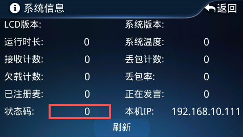
Viewing Status Codes
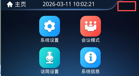
- 20250620 version
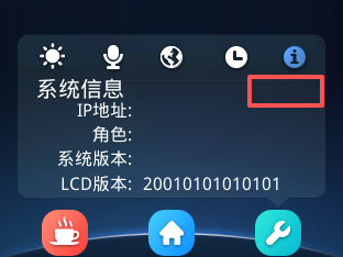
- 20251120 version and later
FAQ (Continuously Updated)
Q: The microphone cannot connect to the network after power-on
A:
- Check whether the AP is powered on;
- Check whether the network cable is in good condition; replace it for testing if necessary;
- Try restoring the microphone to factory settings;
- On the microphone display, tap "Settings" → "System Information", check the system version, and report it to after-sales service personnel;
Q: All indicators of the wireless microphone stay on continuously after power-on
A:
- Check whether the main unit is powered on and whether the network cable is plugged into the WIFI network port;
Q: All indicators of the wired microphone stay on continuously after power-on, or the indicators turn off but the microphone cannot speak, or the network status on the display stays disconnected, or the display shows the network is connected but the microphone cannot connect to the main unit (Note: when using a switch box, a wired microphone shows the network as connected even if the main unit is not connected)
A:
- Check whether the main unit is powered on;
- Check the main unit model — whether it is a wireless-only model (which does not support wired microphone access);
- Check whether the link from the wired microphone to the main unit is normal;
- Check whether the corresponding channel indicator on the front panel is lit; if not, the problem described in the next step is very likely the cause;
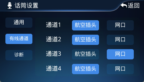
- Confirm whether the main unit's main board supports dynamic switching between the aviation connector and the network port;
- On the main unit display, tap "Microphone Settings" → "Wired Channel", and according to the display configuration, check whether the wired microphone cable is plugged into the correct aviation connector or RJ45 port;
Q: After the microphone powers on, the mic stem, button, and running status indicators all flash rapidly
A:
- This problem generally has 3 possible causes. First check the status code in the upper right corner of the microphone display → "Settings" → "System Information" to determine the cause:
-
- IP conflict (only wired microphones have this problem). When this happens, the microphone automatically increments its own IP by 1; simply restart that microphone. If you still need to set the IP, refer to the "Setting Microphone IP" section;
-
- ID conflict. When this happens, the microphone automatically increments its own ID by 1; simply restart that microphone. If you still need to set the ID, refer to the "ID Assignment" section;
-
- The system has exceeded the maximum number of microphones that can be connected; contact after-sales service personnel;
-
If the system has both wireless and wired microphones, it is recommended to power on all wireless microphones first, wait until they have all connected to the main unit, and then power on all wired microphones. If an IP or ID conflict occurs, simply restart the corresponding wired microphone;
Q: Audio/video quality issues
A:
- Make sure the WiFi is within the effective range: within 50 meters without obstructions;
- Make sure the WiFi signal is 5GHz, not 2.4GHz;
- On the microphone display, tap "Settings" → "System Information"; on the main unit display, tap "System Information" → "Refresh". You can make a preliminary judgment based on the following:
-
- If the packet loss count or packet loss rate grows too fast: the distance between the microphone and the AP is generally too far, or there is interference from other 5G signals; try eliminating the above issues one by one and then test again;
-
- If the underrun count grows too fast: the AP has generally been running for too long, causing overly frequent network packet loss; try restarting the AP;
-
Q: The STATUS indicator of the main unit does not flash after power-on
A: Check whether the network cable connecting the main unit to the wireless router is properly plugged in, whether the network port indicator is lit, and whether the wireless router is powered on;
Q: Cannot log in to the main unit web page
A: Observe the STATUS indicator. If it flashes normally, ping the device's IP address 192.168.10.111 from a computer to first confirm whether the device is running normally;
Q: The main unit display shows only text and no icons
A: The main unit display has two batches: DC48270S043 (old) and DC48270DN043 (new). Distinguish the model and flash the corresponding firmware as needed;
Q: The main unit is powered on and the microphone is powered on and speaking, but the system has no sound output
A: Check in the following order:
- Via the display → System Settings → System Registration, check whether the main unit's trial period has expired;
- Is the rear panel volume knob turned to the minimum position?
- Connect an audio source to any AUDIO IN port on the rear panel — does AUDIO OUT have loopback output?
- Take photos of the main unit display home page and system information page and send them to after-sales service personnel for confirmation;
The following is for professional personnel only:
- Check whether the three arrows on the main unit main board, MCU core board, and DSP core board inside the chassis are assembled in a consistent order;
- Whether the relay is engaged (whether the LED1 indicator on the main unit main board is lit);
- For DCS_SRV_MB_V304 and later main boards:
- Whether J30 is shorted;
Q: The main unit cannot save the time and registration code
A: Check in the following order:
- Is the button cell battery installed, and is the battery voltage around 3V?
- Is the DSP core board inserted in the correct position?
- Check whether the stamp-hole core board is soldered properly;
The following is for professional personnel only:
- Check the main unit main board version inside the chassis: the v305 large base board must be paired with a v205 or later front panel;
Q: An error is prompted after entering the registration code
A: Check in the following order:
- Is the machine code correct?
- Has the main unit's configuration code been set?
- In trial mode, does the main unit time deviate too much from the local time?
Q: The conference management platform web page cannot be opened after installing or restarting the platform
A: Check in the following order:
- Was the conference management platform installed on the default C: drive?
- Check for port conflicts: 1) on Windows, use netstat -ano | findstr 80; 2) on Unix, use netstat -apn | grep 80 to check whether other software on the current system is already using port 80;
Q: The wired microphone cannot connect to the network after power-on
A: Check in the following order:
- Check whether the network wiring is correct;
- Is the main unit's wired channel set to the correct aviation connector or network port;
Q: The main unit display prompts low battery or battery not installed
A: Check in the following order:
- Check whether the CR1220 button cell battery is installed;
- If the CR1220 button cell battery is installed and the factory date is within 12 months, connect to the network where the conference system is located and use the main unit web backend to perform time sync;
Q: After flashing, the system has voice errors, or it gets stuck on the welcome page at startup, or the main unit cannot be pinged
A: Long press the two buttons on the front panel of the main unit until the main unit is restored to factory settings;